User Manual
Control ModuleTemplate - AIN (Analog Input)
A high-end building block for Plant Wide Automation
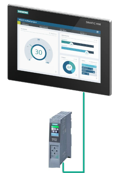
Siemens TIA Portal: PLC code + Program structure ready + HMI Unified graphic object + Pop-up graphic
Modern look and feel – scalable for plant wide professional applications

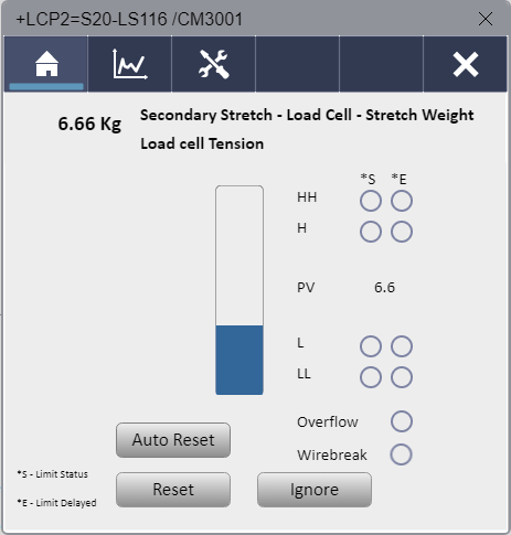
Operator example -

Development example -
Anchor your knowledge, organize, structure and scale up your automation capacity with CEDAS.
Version
| Version | Date | Initials | Description |
| 1.0 | 05-12-2024 | SSA | Document created |
| 1.1 | 22-01-2025 | SSA | Updated CM, Udts, Popup and Scripts |
| 1.2 | 27-01-2025 | PJH | New front cover |
| 1.3 | 31-01-2025 | SSA | Formatted all screenshots with captions |
| 1.4 | 29-09-2025 | SSA | Updated screenshots, Units and Scaling configuration |
Abbreviations
| HMI | Human Machine Interface – Any interaction between machine and operator |
| IO | Electrical Input and Output signals to the control unit (PLC/CPU) |
| DIN | Electrical Digital Input signal, typical 24 VDC. |
| AIN | Electrical Analog Input signal, typical 0-20 mA, 4-20 mA or 0-10V DC |
| AOUT | Electrical Analog Output signal, typical 0-20 mA, 4-20 mA or 0-10V DC |
| MTR | Electrical Control of a Motor with a fixed speed – Direct Online |
| FRQ | Frequency Inverter – Controlling a variable speed motor |
| VLV | Valve Control or Digital Output (Ex. Operating a coil or turning equipment On or Off. |
| PID | A Proportional–Integral–Derivative controller is a widely used in and a variety of other applications requiring continuously modulated control. |
| UN | Unit – A collection of EM’s and/or CM’s that controls a machine functionality ex. a conveyor section or the wrapper. |
| EM | Equipment Module – A collection of CM’s that controls a small machine part or machine section – ex. hoist motors to lift the stretch film rollers. |
| CM | Control Modules are single devices which are electrically controlled and represent Motors, Valves, Inputs or Outputs. |
| FP | Face plate – ex. (CM) control modules are controlled by faceplates represent Motors, Valves, Inputs or Outputs and their status as well as tools for analysis during operation. |
| SP | Set Point – Process request to obtain or aim at this value. |
| PV | Process Value – Process feedback value at this current time = actual value. |
| CV | Control Value – Process regulation value used to adjust/increase or decrease due to an error between the SP and the PV for the given process. |
| +MCC | Main control cabinet |
If you are missing something – please notify us at
Copy to the subject field: AIN – User manual content (version no), and add your comment – we appreciate your help.
Preface
The Package contains the Control Module library, Sample Project, Documentation, Tutorial Video to configure Analog Input in PLC and HMI.
🔒 Please log in to continue reading this document.
Reference link to download
- 🔒 CM_AIN_V1.4_20250929_1742.zal19 (Login to download)
- 🔒 TIA_Unified_CAPP_AIN_V1.41_20250929_2010.zap19 (Login to download)